


An Additional Barrier Against Cesium Release

A second Cs barrier in the fuel matrix captures Cs as pollucite and immobilizes it within the fuel form — without redesigning the qualified TRISO particle.

Key points

Cs gets out — even from intact particles.

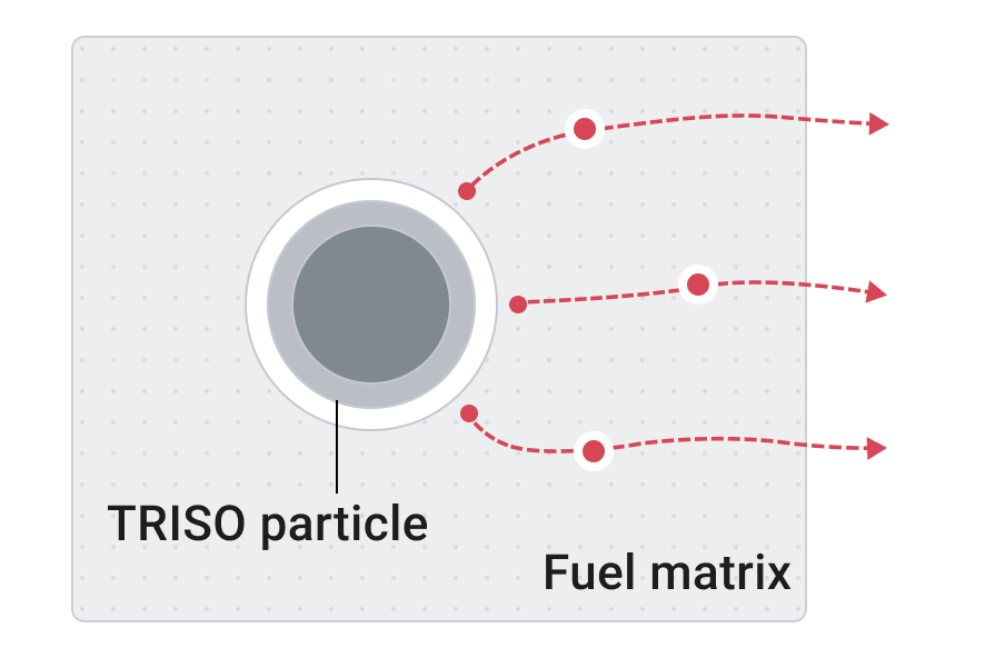
Schematic showing cesium diffusion through intact TRISO coating layers
A fraction of Cs diffuses through intact coating layers.

Cs that leaves the kernel deposits in the primary circuit. About 80 % of the plate-out dose rate there comes from caesium, which drives occupational dose during maintenance (JAERI-M 91-198).

Thicker coatings would help. But TRISO requalification would be required.

Graphite adsorbs Cs. We want it chemically bound.

Add a second Cs barrier — without redesigning TRISO.

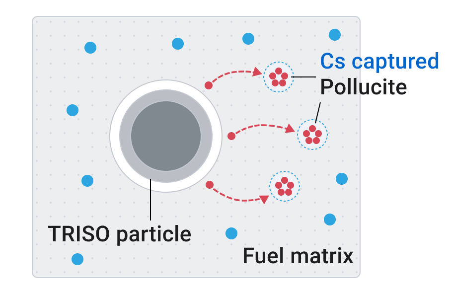
Schematic showing cesium capture as pollucite in the fuel matrix with getter material
Cs + aluminosilicate → CsAlSi2O6 (pollucite)

Aluminosilicate is added to the graphite matrix so Cs can be chemically captured as pollucite before it leaves the fuel element. Cs is immobilized within the fuel form.


Potential benefit of confining Cs within the fuel form

Unlocking new value for HTGRs

Safety benefits

Less Cs in the primary circuit during normal operation and accidents.

Economic benefits

Lower maintenance doses, shielding requirements, and decommissioning waste.

Potential licensing benefits

  • Reduced Cs source term
  • Additional margin in accident consequence evaluations
  • An additional chemical barrier supporting defense-in-depth

And you get there without touching the qualified particle.

Capture first, then test retention at 1600 °C

Step 01

Capture

Graphite + 1 mol% of aluminosilicate (Al2O3·3SiO2) + metallic Cs. Heating at 670 °C × 1 h under Ar (just below the boiling point of Cs) to make the Cs-captured specimen.

Step 02

Retention

1600 °C under Ar (simplified AOO condition) × 1 h, 3 h; 1600 °C under air (simplified air-ingress accident condition) × 1 h. Then: is Cs retained? → checked by SEM-EDS and TEM.

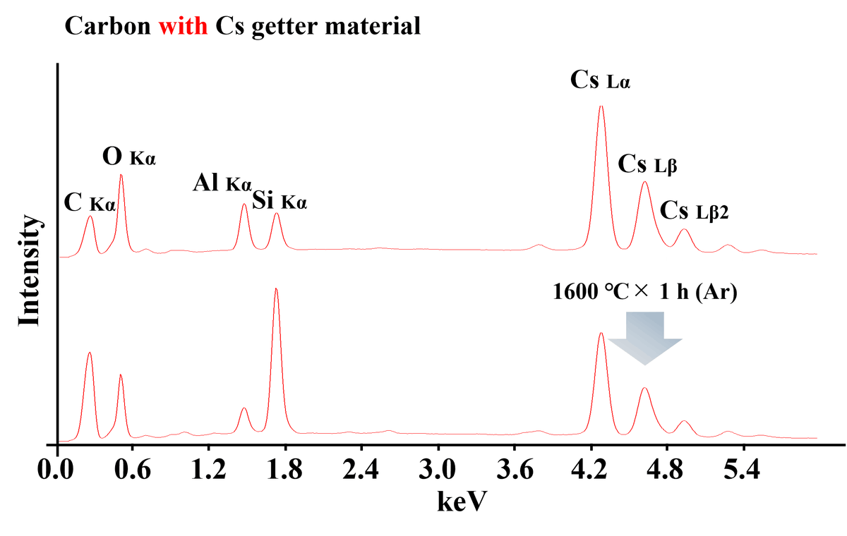
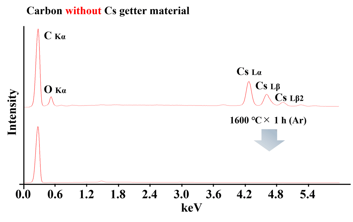
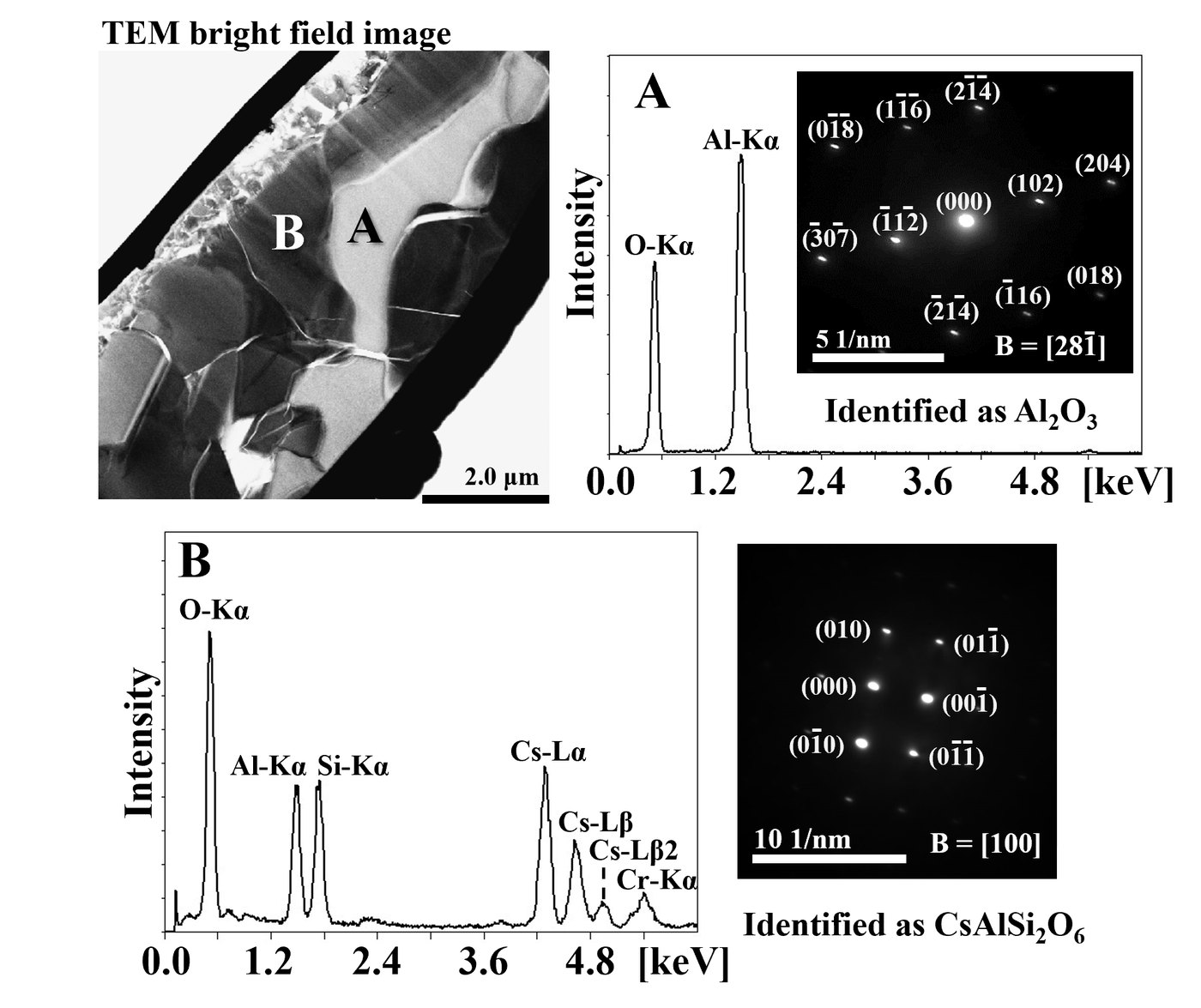
Cs peaks remain in all heated specimens — including 1 h in air. No Cs was detected in the getter-free reference.

With the getter, cesium stays. No getter, no Cs retained.

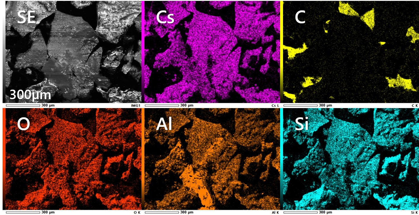
Six EDS element maps after 1600 degrees Celsius for one hour in air showing cesium with aluminium, silicon and oxygen
Six views of the same field, after 1600 °C × 1 h in air. Cs sits where aluminium, silicon and oxygen are — and not on the graphite (C).
SEM-EDS spectra comparison part one SEM-EDS spectra comparison part two
After the same Cs-capture step and 1600 °C × 1 h in Ar, Cs L-lines remain in the getter-containing specimen but are not detected in the getter-free reference.

No Cs detected in the getter-free reference.

What the getter costs the fuel element

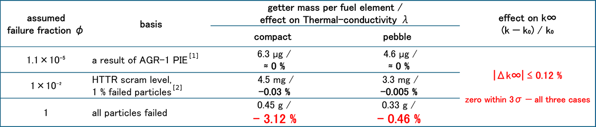
Even under conservative assumptions, the performance penalty remains small.

  • Reactivity

    |Δk∞| ≤ 0.12 %

    zero within 3σ — all three cases.

  • Thermal conductivity

    −3.12 % / −0.46 %

    Even if every particle failed: compact / pebble. Maxwell–Eucken estimate; 0.03 % or less at the 1 % failed-particle case.

  • Maintenance dose

    η = 0.63

    Capture efficiency that would halve the primary-circuit dose rate in the preliminary assessment.

Getter mass per fuel element, the estimated effect on thermal conductivity, and the effect on k∞, by assumed failure fraction

Chart of getter mass, thermal conductivity effect and reactivity effect by failure fraction

The table is the same basis used in the TopFuel 2026 presentation. [1] Demkowicz et al., HTR-2016, INL/CON-16-38197 (2016), Table 2. [2] IAEA-TECDOC-1674 (2012), §5.1.4.2 — scram level 7×10⁴ MBq/m³ ≡ 1 % failed particles.

What is confirmed, and what is fuel-form specific

Validation area Present evidence Next need
◆ Fuel form & matrix properties Powder mixing, lab scale Mockups; density, strength, thermal conductivity, porosity and the temperature window for getter-phase stability in graphite before capturing cesium.
Cs retention Pollucite confirmed, 1600 °C, Ar & air Quantitative retention (η: fraction of Cs captured by the getter)
◆ Irradiation stability Out-of-pile only In-pile stability, PIE
◆ Fuel performance & source term Loading parameterized by Cs inventory Reactor-specific assessment

◆ = fuel-form specific. Cannot be closed without the fuel designer's input. Underlined: tasks currently in progress.

Take-home message

  1. 01

    A second Cs barrier can be added without redesigning TRISO. Aluminosilicate captures Cs as pollucite, confirmed after 1600 °C exposure in Ar and air.

  2. 02

    Confining Cs within the fuel form unlocks new value for HTGRs. Less Cs in the primary circuit; lower maintenance dose, shielding and decommissioning waste; potential licensing benefits.

  3. 03

    The estimated performance penalty is small. No measurable reactivity penalty; and a thermal-conductivity penalty that stays small even under conservative assumptions.

  4. 04

    The remaining step is fuel-form integration. Getter loading, matrix properties and processing window must be optimized with the fuel designer.

The chemistry is demonstrated. The next step is integration into a real fuel design.

Answer these three, and we can size the getter for your fuel.

  1. 01How much reduction in the cesium source term are you aiming for?
  2. 02What particle failure fraction do you design for?
  3. 03Which fuel form — pebble, or compact?

We can start from a single specimen made to your spec.

Discuss a technical collaboration

Answer as many of the three design questions as you can.
Anything left blank can be discussed directly.

Fuel matrix fabrication → Cs retention testing → irradiation stability → fuel-form validation.

Japan Patent No. 7672601

PCT International Publication: WO 2026/176857 A1

View on WIPO PATENTSCOPE

FAQ

Frequently Asked Questions